

The Engineer’s Guide to AC Power Cord AWG Selection: Ampacity, Voltage Drop & Thermal Derating
Content Menu
● Introduction: Why Sizing an AC Power Cord Involves More Than Just Amperage
● 1. Demystifying AWG: The Foundation of North American Cable Standards
>> 1.1 What is American Wire Gauge (AWG)?
>> 1.2 Geometric Proportions of AWG Sizes
● 2. Step 1: Establishing Base Ampacity and the Weakest Link Principle
>> 2.1 Understanding Cable Ampacity and Insulation Ratings
>> 2.2 Standard Conductor Ampacity Reference (for Power Cords)
>> 2.3 The Weakest Link Principle
>> 2.4 Continuous Load Factor (80% Rule)
● 3. Step 2: Ambient Thermal Derating
>> 3.1 I²R Heating and Thermal Limits
>> 3.2 Ambient Temperature Correction Factors
>> 3.3 Case Study: High-Temperature Environment
● 4. Step 3: Bundle Derating for Multi-Cord Installations
>> 4.2 Adjustment Factors (Current-Carrying Conductors)
● 5. Step 4: Voltage Drop Calculations
>> 5.2 Formula for Single-Phase AC
>> 5.3 Example: 12A Load, 15m Cord, 120V
● 6. Comprehensive Selection Guide: 18 AWG vs. 16 AWG vs. 14 AWG
● 7. Matching AWG to NEMA Standards
● 8. B2B OEM Engineering Process
● 9. Frequently Asked Questions (FAQ)
Introduction: Why Sizing an AC Power Cord Involves More Than Just Amperage
When international B2B buyers and electrical engineers source North American AC power cords for industrial machinery, medical devices, or data center servers, the question often arises: Our equipment draws 10 Amps, so a standard 10A-rated power cord should be fine, right?
As a custom AC power cord manufacturer with over two decades of engineering and production experience, my answer is consistent: Selecting an American Wire Gauge (AWG) based solely on nominal amperage risks system failure, compliance rejection, or thermal issues.
A certified North American power cord is a complex thermal-electrical system. Proper AWG selection requires balancing:
- Continuous vs. non-continuous loads
- Conductor base ampacity
- Insulation temperature ratings
- Ambient temperature adjustments
- Bundle derating factors
- Maximum permissible voltage drop (ΔV)
- Safety agency compliance (UL 817, CSA C22.2, NEC)
This guide provides the precise engineering framework for optimal AWG selection, ensuring safety, efficiency, and regulatory compliance.
1. Demystifying AWG: The Foundation of North American Cable Standards
1.1 What is American Wire Gauge (AWG)?
The American Wire Gauge (AWG) system standardizes wire diameters for round, solid, nonferrous conductors in North America. It uses a logarithmic inverse scale: larger gauge numbers indicate smaller conductor diameters, resulting in higher resistance and lower current capacity.
1.2 Geometric Proportions of AWG Sizes
Every three-gauge decrease roughly doubles the cross-sectional area, halves resistance, and doubles current capacity. Key attributes for common AC power cord gauges:
| AWG Size | Conductor Diameter (mm) | Cross-Sectional Area (mm²) | Nominal Resistance at 20°C (Ω/km) | Typical B2B Applications |
|---|---|---|---|---|
| 18 AWG | 1.024 | 0.823 | 20.95 | Small electronics, LED displays, low-power chargers |
| 16 AWG | 1.291 | 1.31 | 13.18 | PC power supplies, networking equipment, medical monitors |
| 14 AWG | 1.628 | 2.08 | 8.28 | Data center PDUs, industrial machinery, heavy-duty tools |
2. Step 1: Establishing Base Ampacity and the Weakest Link Principle

2.1 Understanding Cable Ampacity and Insulation Ratings
Ampacity is the maximum continuous current a conductor can carry without exceeding its temperature rating (per NEC). Limits stem from insulation degradation (PVC, TPE, etc.), not copper melting.
2.2 Standard Conductor Ampacity Reference (for Power Cords)
Typical values for flexible cord assemblies (aligned with UL 817 and common practice):
| AWG Size | 60°C Insulation | 75°C Insulation | 90°C Insulation (e.g., SJT) |
|---|---|---|---|
| 18 AWG | 10A | 12A | 14A |
| 16 AWG | 13A | 15A | 18A |
| 14 AWG | 15A | 20A | 25A |
| 12 AWG | 20A | 25A | 30A |
| 10 AWG | 30A | 35A | 40A |
2.3 The Weakest Link Principle
The entire assembly rating follows the lowest-rated component (UL 817 / CSA C22.2). A 14 AWG 90°C wire with a 15A NEMA 5-15P plug is limited to 15A overall.
2.4 Continuous Load Factor (80% Rule)
Per NEC guidelines for continuous loads (≥3 hours), limit to 80% of nominal rating:
A 15A cord suits up to ~12A continuous duty (e.g., servers, refrigeration).
3. Step 2: Ambient Thermal Derating
3.1 I²R Heating and Thermal Limits
Current generates heat (I²R). Elevated ambient temperatures reduce heat dissipation, risking insulation failure.
3.2 Ambient Temperature Correction Factors
Apply multipliers from NEC Table 310.15(B)(1) (baseline 30°C):
| Ambient Temp (°C) | 60°C Factor | 75°C Factor | 90°C Factor |
|---|---|---|---|
| 30°C | 1.00 | 1.00 | 1.00 |
| 40°C | 0.82 | 0.88 | 0.91 |
| 50°C | 0.58 | 0.75 | 0.82 |
| 60°C | - | 0.58 | 0.71 |
| 70°C | - | - | 0.58 |
3.3 Case Study: High-Temperature Environment
14 AWG, 90°C insulation at 70°C ambient:
- Base: 25A
- Factor: 0.58
- Adjusted: 14.5A
In hot industrial enclosures, capacity drops significantly—plan accordingly to avoid degradation.
4. Step 3: Bundle Derating for Multi-Cord Installations
4.1 Mutual Heating Effects
Bundled cords in racks or trays create heat traps, requiring derating.
4.2 Adjustment Factors (Current-Carrying Conductors)
| Number of Conductors | Derating Factor |
|---|---|
| 4–6 | 80% (0.80) |
| 7–9 | 70% (0.70) |
| 10–20 | 50% (0.50) |
| 21–30 | 45% (0.45) |
Manufacturers validate via thermal chamber testing and cyclic aging.
5. Step 4: Voltage Drop Calculations
5.1 Why Length Matters
Longer runs increase resistance, causing voltage drop that leads to malfunctions or inefficiency.
ΔV=I×Rcable
5.2 Formula for Single-Phase AC
ΔV=2×I×L×(1000R)
(NEC recommends ≤3% for branch circuits.)
5.3 Example: 12A Load, 15m Cord, 120V
18 AWG (R=20.95 Ω/km): ~6.28% drop (excessive).14 AWG (R=8.28 Ω/km): ~2.48% drop (acceptable).
6. Comprehensive Selection Guide: 18 AWG vs. 16 AWG vs. 14 AWG
| Feature | 18 AWG | 16 AWG | 14 AWG |
|---|---|---|---|
| Max Typical Rating | 10A | 13A | 15A |
| Flexibility | High | Balanced | Lower |
| Cost | Low | Medium | Premium |
| Best For | LEDs, office equipment | PCs, switches, instruments | Servers, PDUs, machinery |
7. Matching AWG to NEMA Standards
| NEMA Type | Rating | Recommended AWG | Applications |
|---|---|---|---|
| 5-15P | 125V/15A | 18/16/14 | General commercial |
| 5-20P | 125V/20A | 14/12 | High-draw equipment |
| L6-20P | 250V/20A | 14/12 | Industrial/racks |
| L6-30P | 250V/30A | 10 | High-power infrastructure |
8. B2B OEM Engineering Process
Our six-step workflow ensures compliance:
1. Load analysis
2. Environment profiling
3. Thermal calculations
4. Bundle assessment
5. Voltage drop verification
6. Certification & construction
9. Frequently Asked Questions (FAQ)
Q1: Why not use 18 AWG for a continuous 10A load over distance?
High resistance causes excessive voltage drop and reduced safety margins in real environments.
Q2: Is larger AWG always better?
No—over-specifying adds weight, stiffness, and cost without proportional benefits.
Q3: Why does a UL-certified cable assembly still require an independent factory thermal test?
A raw copper wire receiving a UL component certification merely means the raw material meets baseline insulation tests in isolation. Once that wire is cut, stripped, crimped onto metal terminals, and over-molded into a finished NEMA plug assembly, new variables are introduced. Poor termination crimps or tight plastic over-molding can create localized resistance. Independent factory thermal testing validates the entire completed system under full functional load.
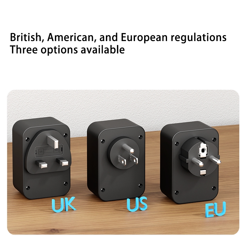
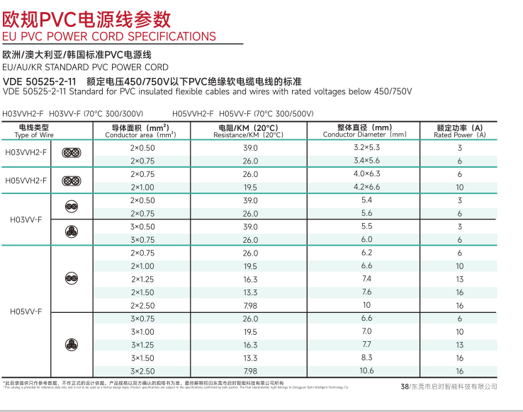
Q4: What is the main structural difference between North American AWGcables and European mm2 Harmonized cables?
AWG is based on an inverse logarithmic scale designed around wire-drawing manufacturingprocesses, whereas European harmonized standards (HO5W-F, etc.) size conductors directly bytheir true metric cross-sectional area (mm2). For example, a standard European 0.75 mm2cable does not exactly match a North American gauge; it sits between 18 AWG (0.823 mm2)and 19 AWG, requiring distinct safety agency evaluations for transatlantic product exports.
Q5: How do environmental regulations like RoHS and REACH impact AWG power cord selection?
RoHS and REACH do not directly alter the copper wire gauge dimensions, but they heavily restrict the chemical plasticizers, heavy metals, and flame retardants used in the outer PVC/rubber jackets. When designing an optimal AWG power cord for international markets, you must ensure that your manufacturer balances the copper diameter with eco-compliant, flame-retardant compounding jackets to pass both electrical and chemical regulatory checks simultaneously.
References
1. National Fire Protection Association (NFPA). NFPA 70: National Electrical Code (NEC) 2023.
2. Underwriters Laboratories. UL 817: Standard for Cord Sets and Power-Supply Cords.
3. CSA Group. CSA C22.2 No. 21: Cord Sets and Power-Supply Cords.
4. ANSI C84.1: Electric Power Systems – Voltage Ratings.


 Email
Email