


Data Center PDU Power Cords: C13, C14, C15, C19 & C20 Guide
Content Menu
● What Is a Data Center PDU Power Cord?
● C13, C14, C15, C19 and C20 Explained
● C13/C14 vs C19/C20: Which Should You Choose?
● How to Choose the Right Data Center PDU Power Cord
● PDU Power Cords for AI Data Centers
● Data Center PDU Power Jumpers
● Data Center Power Cord and Cable Management
● How to Build a Data Center Power Cord Strategy
● Custom Data Center PDU Power Cords from a Source Manufacturer
● FAQ
Modern data centers depend on a critical but often overlooked component to keep servers and network equipment running: the power cord that connects the rack PDU to each device. While PDUs receive most of the design attention, the cables that complete the electrical path are equally important.
As rack densities rise—especially in AI and high-performance computing environments—selecting the right connector type, conductor size, cable construction, and locking features becomes essential. A mismatched power cord can introduce unnecessary resistance, complicate maintenance, or create a weak point in an otherwise well-designed power system.
This guide explains what a data center PDU power cord is, how C13, C14, C15, C19, and C20 connectors are used, when to choose each configuration, and how engineers and procurement teams can select and standardize the right cables for reliable rack-level power distribution.
What Is a Data Center PDU Power Cord?
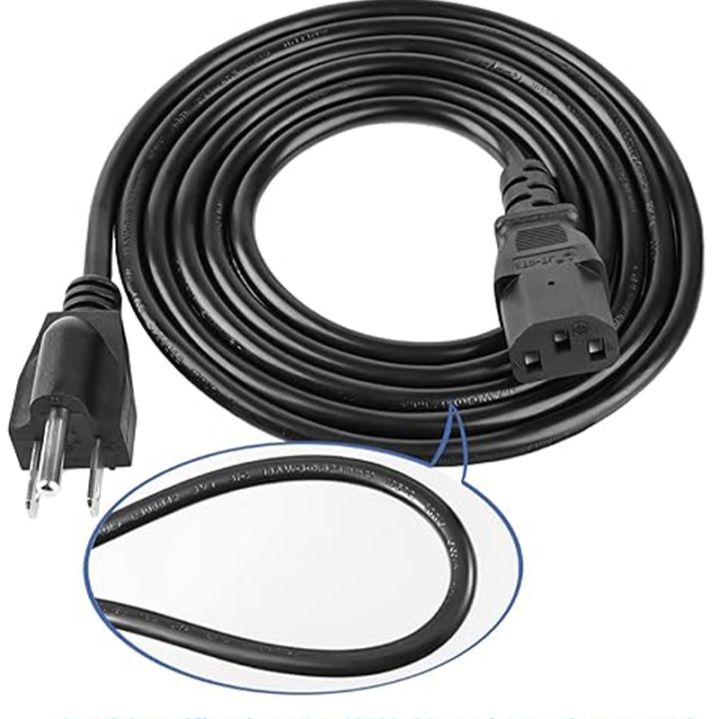
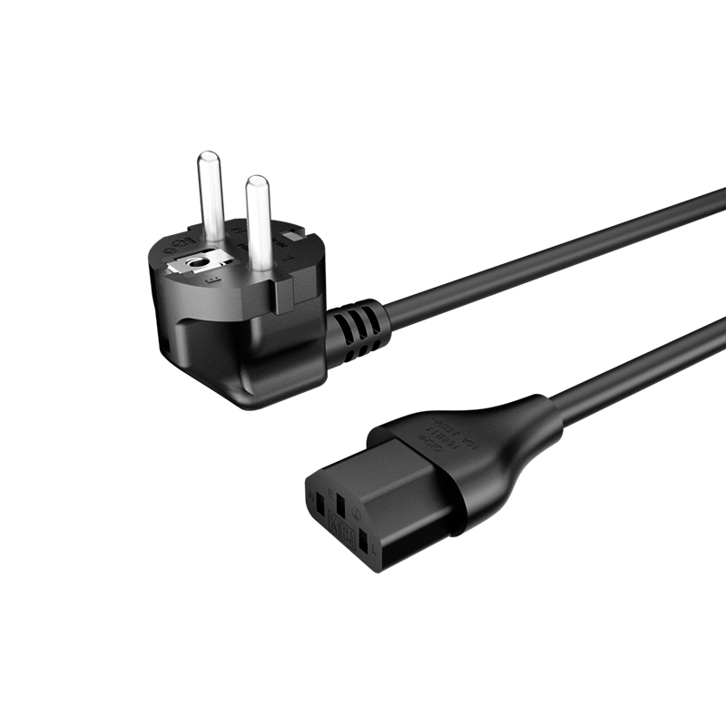
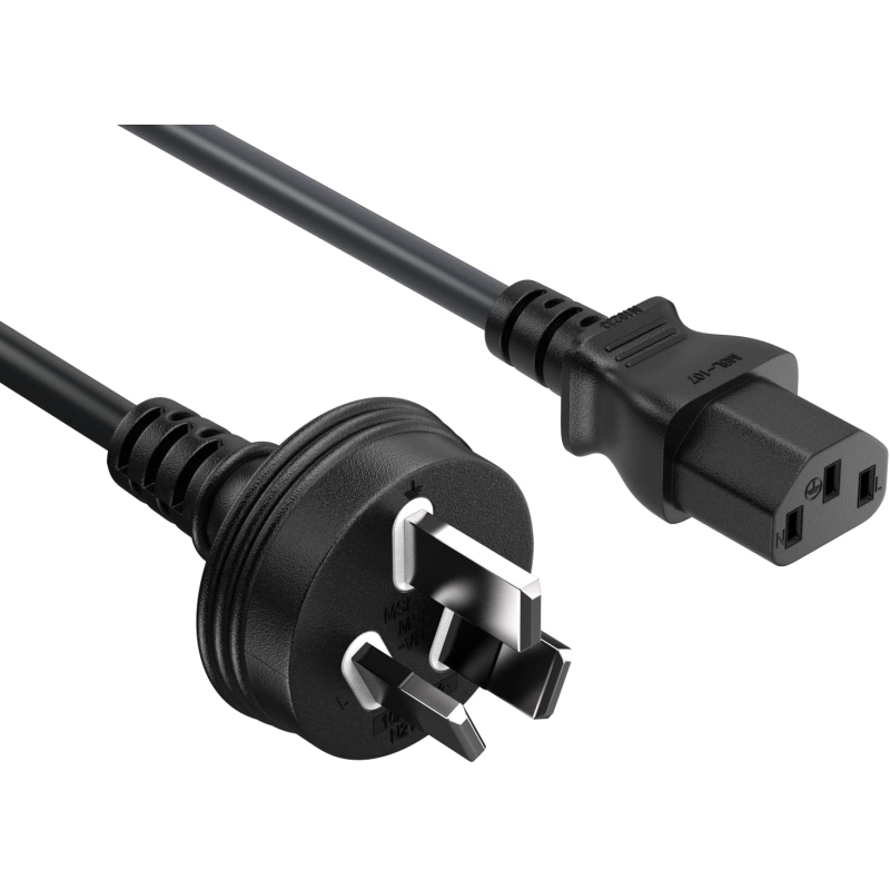
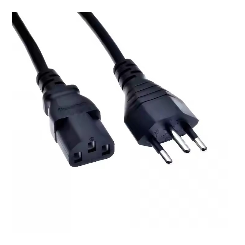
A data center PDU power cord is the final link in the rack power path. It connects the outlets on a power distribution unit to the inlets on servers, storage systems, switches, and other IT equipment.
The relationship is straightforward:
PDU → Power Cord → IT Equipment
The PDU itself is only part of the electrical system. Upstream power feeds the PDU; the PDU distributes power through its outlets; and the power cord delivers that power to the equipment inlet. Because this final connection must carry the expected current, match the connector interfaces, and remain reliable under continuous load, cable selection should be treated as part of the overall data center power design rather than an afterthought.
In practice, the power cord is not a passive accessory. Conductor size, insulation, contact resistance, temperature rating, length, and connector quality all influence long-term reliability. Standardized, correctly specified data center power cords also simplify installation, inventory management, and maintenance across large facilities.

C13, C14, C15, C19 and C20 Explained
These connectors belong to the IEC 60320 family of appliance couplers. They are widely used because their standardized form factors support consistent deployment across international data center environments. Selection should never be based solely on physical fit—electrical ratings of the complete cable assembly, PDU outlet, and equipment inlet must all align.
C13/C14 Power Cords
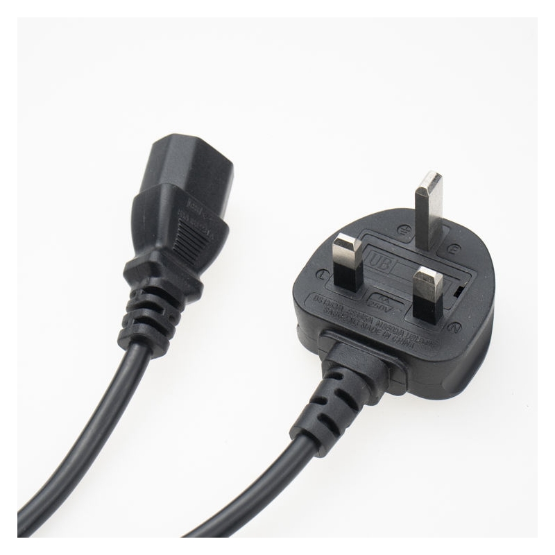
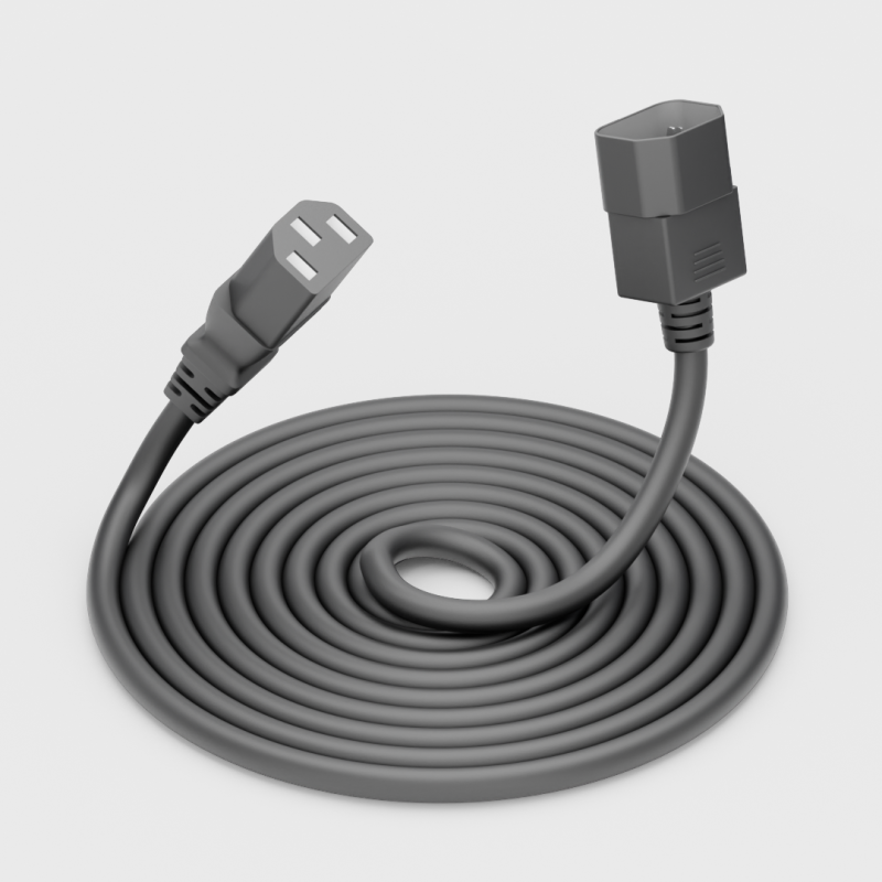
C13 and C14 connectors remain the most common combination for standard data center racks. In a typical configuration, the PDU provides C13 outlets and the equipment uses a C14 inlet. The corresponding cable is therefore a C14-to-C13 power cord (or the reverse orientation depending on which end is described).
These cords are widely used with:Standard rack servers Network switches Storage systems KVM and telecommunications equipment Monitors and general rack accessories
C13/C14 power cords suit equipment operating within the electrical ratings of the complete assembly. Facilities with large numbers of similar racks often standardize on these components to simplify spare-part inventory and cable management.

C15/C14 Power Cords
C15 connectors look similar to C13 but use a different keying design. This mechanical difference prevents them from being treated as fully interchangeable and supports higher-temperature appliance-coupler applications when the equipment manufacturer specifies a C15 (or compatible C16) inlet.
C14-to-C15 power cords are appropriate when:
- The equipment inlet is rated for higher temperature
- The manufacturer explicitly requires a C15 connection
- The application involves elevated ambient or inlet temperatures
Data center operators should not select C15 simply because a rack runs warm. Always verify the equipment inlet specification and the full cable assembly rating.
C19/C20 Power Cords
As rack power requirements increase, C19 and C20 connectors become more relevant. In the common high-power configuration, the PDU supplies C19 outlets and the equipment uses a C20 inlet, so the cable is a C20-to-C19 power cord.
These cords are typically used with:Higher-power servers UPS systems and power supplies High-density compute platforms AI and HPC infrastructure
C19/C20 components support higher-current applications within their rated limits and are increasingly specified in modern high-density racks.

C13/C14 vs C19/C20: Which Should You Choose?
| Item | C13/C14 | C19/C20 |
|---|---|---|
| Typical application | Standard IT equipment | Higher-power equipment |
| Rack density | Standard | High-density |
| Typical equipment | Servers, switches, storage | High-power servers, UPS, AI infrastructure |
| PDU configuration | C13 outlets | C19 outlets |
| Selection priority | Equipment and system rating | Equipment and system rating |
Neither combination is universally "better." C13/C14 remains the practical choice for conventional IT loads. C19/C20 is selected when equipment power levels and system design require the higher-capacity interface. Mixed C13/C19 PDUs are common when racks contain both standard and high-power devices.
How to Choose the Right Data Center PDU Power Cord
Engineers should evaluate the complete power path rather than any single component. The following sequence reflects typical selection practice.
Check the PDU Outlet
Confirm whether the rack PDU uses C13, C19, or a mixed configuration. The outlet type determines the cable end that plugs into the PDU.
Check the Equipment Inlet
Identify the inlet on each major device (C14, C16/C15-compatible, C20, or other). Mismatched connectors cannot be forced without risk.
Confirm Voltage and Current Requirements
Match the cable assembly rating to the expected system voltage and current. The limiting factor is always the lowest-rated component in the chain—PDU outlet, cable, connectors, and equipment inlet.
Select the Appropriate Conductor Size
Conductor size (AWG or metric) must support the continuous current without excessive voltage drop or heating. High-density applications often require different construction from standard server cords.
Check Cable Temperature Rating
Verify that the cable's temperature rating is suitable for the rack environment and any elevated inlet temperatures specified by the equipment manufacturer.
Select the Correct Cable Length
Length should allow proper routing without excess slack that creates clutter or insufficient length that stresses connectors. In high-density racks, precise length control improves airflow and maintenance access.
Consider Locking Connectors
Where accidental disconnection carries operational risk, locking C13/C14 or C19/C20 connectors provide additional mechanical security. Locking features complement—not replace—proper cable management.
Confirm Certifications and Regional Requirements
Ensure the complete assembly meets the applicable safety certifications and regional standards for the deployment location.
The final electrical capability is determined by the complete cable assembly, not by the connector designation alone.
PDU Power Cords for AI Data Centers
AI servers draw significantly more power than traditional enterprise servers. This change affects the entire rack power path: PDU input capacity, branch-circuit protection, outlet configuration, connector selection, conductor size, temperature rating, and cable management all become more critical.
Higher rack density means fewer devices can share a given power budget, so many AI deployments shift toward C19 outlets and corresponding C19/C20 power cords. Cable construction must support the higher continuous currents while remaining manageable alongside network cabling and, in some cases, liquid-cooling infrastructure.
Thermal management also gains importance. Power cords should not obstruct airflow or create hot spots. In liquid-cooled systems, routing must coexist with manifolds, hoses, and service clearances. Standardized, correctly rated AI data center power cords reduce the risk of under-specified connections repeating across hundreds of identical racks.
Monitoring remains essential. Intelligent PDUs that measure voltage, current, power, and energy consumption help operators track actual rack demand as AI workloads change over time.
Data Center PDU Power Jumpers
A PDU power jumper (or power jumper cable) is a factory-assembled cable designed for specific distribution applications. It typically combines a defined length, conductor size, connector configuration, and optional features such as labeling or locking connectors.
Factory-assembled jumpers offer several practical advantages for large facilities:
- Consistent cable length and construction across racks
- Specified conductor size matched to the load
- Molded or assembled connectors with controlled quality
- Identification labels for PDU source, phase, or circuit
- Optional locking connectors
- Factory electrical testing of continuity, grounding, and insulation
This approach reduces field assembly variation and shortens installation time. When hundreds or thousands of identical connections are required, standardized power jumpers improve both reliability and maintainability.
Data Center Power Cord and Cable Management
Even correctly specified cords can create operational problems if they are poorly managed. In high-density racks, power cables compete for space with network cabling and cooling infrastructure.
Effective practices include:
- Routing power cables away from equipment access points and unnecessary bends
- Selecting lengths that provide service slack without excess coils;
- Applying clear labels that identify PDU source, outlet number, destination, phase, rack, and circuit
- Avoiding obstruction of airflow or cooling components
- Planning for dual-power (A/B) redundancy so each path remains identifiable
Consistent labeling and standardized configurations significantly reduce troubleshooting time during maintenance windows.
How to Build a Data Center Power Cord Strategy
A mature strategy begins before equipment arrives on site. The following checklist supports systematic selection:
1. Identify equipment — Create an inventory of each device's inlet type and expected power draw.
2. Define PDU architecture — Determine whether racks need C13, C19, or mixed outlets; define input voltage, capacity, branch protection, monitoring, and redundancy.
3. Select cable configuration — Match C13/C14, C14/C15, C19/C20, or other combinations to the PDU outlets and equipment inlets.
4. Confirm cable specifications — Verify conductor size, insulation, temperature and voltage ratings, connector ratings, and required certifications.
5. Plan cable management — Establish lengths and routing paths before installation; avoid excess slack and mechanical stress.
6. Test before deployment — Prefer factory-tested assemblies so continuity, grounding, insulation, and connector integrity are verified before the cables reach the rack.
This process is especially valuable in large AI facilities, where a single specification error can be repeated across many identical connections.
Custom Data Center PDU Power Cords from a Source Manufacturer
Facilities that standardize on specific configurations often benefit from custom or semi-custom power cords. A source manufacturer can support:
- C13/C14, C14/C15, and C19/C20 configurations
- Custom cable lengths
- Specified conductor sizes
- Locking or non-locking connector options
- Labeling for source, phase, circuit, or asset identification
- OEM/ODM requirements
- Factory assembly and electrical testing
- Bulk production for consistent multi-rack deployments
Working from a clear equipment and PDU specification allows the manufacturer to deliver assemblies that match the engineered design rather than relying on generic off-the-shelf lengths and constructions.
Looking for custom C13/C14 or C19/C20 PDU power cords for your data center project? Contact TISDLIP to discuss cable specifications, samples and bulk production.
FAQ
What is a C13 power cord used for?
C13 power cords typically connect PDU outlets to servers, switches, storage, and other IT equipment that use compatible C14 inlets.
What is the difference between C13 and C14?
C13 is commonly the connector that plugs into a PDU outlet; C14 is the corresponding equipment inlet. Together they form the most common standard data-center power-cord combination.
What is the difference between C13 and C15?
C15 uses a different keying design and is intended for higher-temperature appliance-coupler applications when the equipment manufacturer specifies it. The two are not fully interchangeable.
What is a C19/C20 power cord?
A C19/C20 power cord connects higher-power equipment (C20 inlet) to a PDU that provides C19 outlets, or the matching orientation required by the specific system.
When should I use C19 instead of C13?
Use C19 when the equipment inlet and system design require the higher-capacity interface typical of high-power servers, UPS units, and dense compute platforms.
Can C13 and C19 be used interchangeably?
No. They differ in physical size and electrical characteristics. Connectors must match both the PDU outlet and the equipment inlet.
What is a PDU power jumper?
A PDU power jumper is a factory-assembled cable with defined length, conductor size, connectors, and optional labeling or locking features, intended to simplify and standardize rack power connections.
How do I choose the correct PDU power cord?
Match the PDU outlet and equipment inlet, confirm voltage and current requirements of the complete assembly, select appropriate conductor size and temperature rating, choose a practical length, and verify certifications.
Are C19/C20 power cords suitable for AI data centers?
Yes, when the full cable assembly rating matches the AI servers, PDU, branch circuits, and upstream power system. High-density AI deployments require system-level planning of connectors, cables, and thermal management.
What should I consider when ordering custom data center power cords?
Define connector configuration, length, conductor size, temperature rating, locking requirements, labeling, certifications, quantity, and spare inventory needs before placing the order.
Conclusion
C13, C14, C15, C19, and C20 connectors each serve distinct roles in modern rack power infrastructure. C13/C14 remains the practical choice for many standard IT loads; C15 addresses specific higher-temperature requirements; and C19/C20 supports the higher power levels increasingly found in dense and AI-focused deployments.
A data center PDU power cord is not a secondary accessory—it is an integral part of the electrical path from facility power through the PDU to each load. Correct selection requires matching connectors, electrical ratings, cable construction, length, and management practices to the actual equipment and system design.
By treating power cords as engineered components—standardized where possible, customized where necessary, and verified before deployment—operators build more reliable, maintainable, and scalable rack power systems.



 Email
Email