

Content Menu
● 1. Type F, Type E and CEE 7/7: Why the Distinction Matters for Internal Frames
● 2. What Is an EU Plug Internal Frame and Why Fit Matters
● 3. Root Causes of Plastic Leakage and Molding Flash (Document-Based Analysis)
● 4. Step-by-Step Troubleshooting Workflow for Flash and Leakage
● 5. Preventive Design and Quality-Control Practices
● 6. What B2B Buyers Should Verify When Sourcing EU Plug Internal Frames
● 7. OEM/ODM Development Recommendations
● Conclusion and Call to Action
CEE 7/7 European Plug Internal Frame: Injection Molding Flash, Plastic Leakage Causes and Practical Fit Solutions
European plug components demand tight dimensional control and reliable mold sealing. For manufacturers of power cords, plug assemblies and electrical accessories, the EU plug internal frame (especially the French-style / CEE 7/7 hybrid version commonly called "法国头" in production) is a critical insert-molding part. When the internal frame does not sit flush on the mold strip, molten plastic escapes and creates plastic leakage or molding flash (披锋).
This guide draws directly from a practical manufacturing document on French plug internal-frame leakage and flash. It explains the root causes, a proven inspection sequence, and what B2B buyers should verify when sourcing CEE 7/7 or Type F Schuko components.

1. Type F, Type E and CEE 7/7: Why the Distinction Matters for Internal Frames
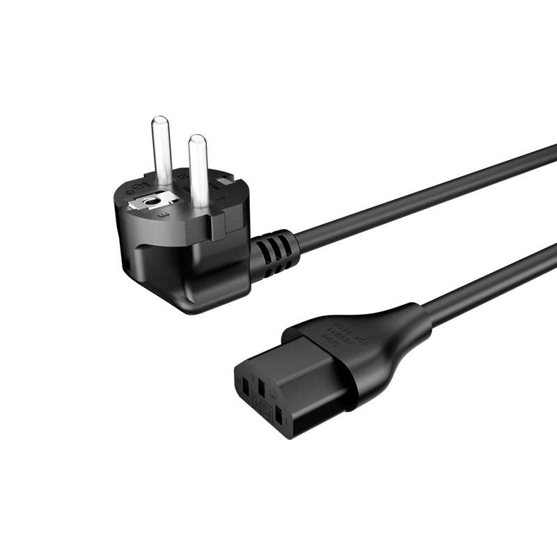
Type F (Schuko, CEE 7/4) uses two round power pins and side protective-earth contacts.
Type E (French, CEE 7/5–7/6) uses two round pins plus a central hole that accepts the protruding earth pin of the socket.
CEE 7/7 is the hybrid plug that combines both: side earth contacts for Type F sockets and a central earth-pin opening for Type E sockets. It is the most widely produced European grounded plug today.
In Chinese manufacturing the term "法国头" frequently refers to the CEE 7/7 hybrid or pure Type-E style frame. The geometry of the internal frame, spring contacts and locating features must match the chosen standard. A frame designed for one configuration cannot be assumed interchangeable with another without drawing verification.
2. What Is an EU Plug Internal Frame and Why Fit Matters
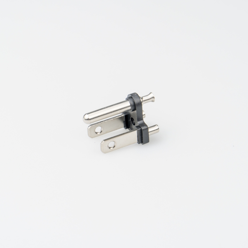
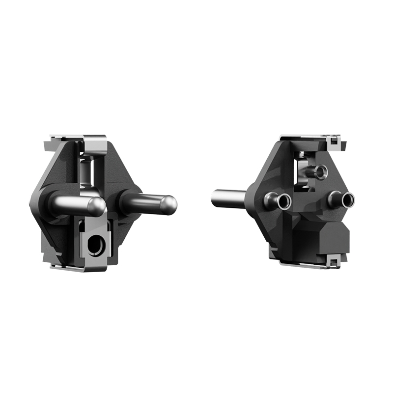
An EU plug internal frame is the metal or pre-assembled insert that positions the conductive parts and provides the sealing interface for subsequent plastic injection. Critical features include:
Dimensional consistency of the frame body 、Position of spring contacts (弹片) 、Radiused corners (R-corners) 、 Alignment of the grounding / earth-pin hole and locating pins
If the frame does not seat tightly against the mold strip (模条), a gap forms. Plastic flows into that gap during injection, producing leakage or flash. The resulting excess material can affect appearance, require rework, or interfere with final assembly dimensions.
3. Root Causes of Plastic Leakage and Molding Flash
3.1 Gap between internal frame and mold strip
Place the internal frame on the matching mold strip and check for tight contact. A visible gap allows plastic to escape. This is the first and most direct inspection point.

3.2 Mismatch between spring contact and R-corner
The most common geometric cause of the gap is an R-corner (radiused feature) that does not properly match the spring contact (弹片). When these two features are not adjusted to fit each other, the frame cannot sit flush. Correct matching produces the tight contact shown in the document's "good-fit" photographs.

3.3 Oversized or misaligned grounding pin
If the spring contact and R-corner are already correct, inspect the grounding pin (地线顶针). An oversized pin can shift and press against the edge of the earth-contact hole, lifting the frame off the mold surface.

Disassemble the mold strip, remove the grounding pin, and re-test the frame fit.
- If the frame now seats tightly → the pin is the cause; reduce its diameter so it no longer contacts the hole edge while still meeting design tolerances.
- If the gap remains → the pin is not the primary problem; reassess other sources.


4. Step-by-Step Troubleshooting Workflow for Flash and Leakage
Follow this sequence exactly as outlined in the manufacturing document. All work on mold tooling must be performed by qualified personnel under appropriate safety procedures.
1. Locate the defect
Record where flash or leakage appears relative to the frame, spring contacts, R-corners and grounding-pin area.
2. Check frame-to-mold-strip fit
Place the actual production internal frame on the corresponding mold strip. Look for any gap, rocking or incomplete contact.
3. Inspect spring contact and R-corner
Verify that the radiused feature and spring contact are dimensionally matched. Adjust only after confirming interference; preserve required contact geometry and function.
4. Test the grounding pin
Remove the pin and repeat the fit check. If fit improves, the pin diameter or position needs correction. Any size reduction must still satisfy the approved drawing and electrical safety requirements.
5. Reassess remaining causes
If the frame still does not seat after the above steps, examine frame dimensional variation, mold-surface condition, debris or other mechanical interference. Injection parameters become relevant only after mechanical fit is confirmed.
6. Verify the correction
Re-assemble, mold trial parts, and confirm: Frame seats tightly on the mold strip 、Flash/leakage is eliminated or reduced to acceptable limits 、Finished dimensions and electrical function remain within specification
5. Preventive Design and Quality-Control Practices
Beyond reactive troubleshooting, manufacturers can reduce recurrence through:
- First-article fit verification – Always check a new or revised internal frame on the actual mold strip before full production.
- Drawing control – Critical R-corner radii, spring-contact height and grounding-pin diameter must be clearly dimensioned and toleranced.
- Tooling maintenance – Keep mating surfaces clean; inspect for wear or damage when the same flash location reappears.
- Traceability – Record mold number, frame revision, defect location, corrective action and verification result.
6. What B2B Buyers Should Verify When Sourcing EU Plug Internal Frames
Before placing volume orders, request the following:
- Exact plug designation (CEE 7/7 hybrid, pure Type F, or pure Type E)
- Approved engineering drawings with critical dimensions and revision status
- Evidence of mold-strip fit checks for the specific frame
- Inspection criteria for flash, leakage and dimensional deviation
- Sample approval process covering fit, appearance and functional requirements
- Applicable certifications and destination-market standards for the finished plug or cord set
A supplier that can explain its mold-interface verification and defect-troubleshooting method demonstrates stronger process control than one that only shows finished-part photos.
7. OEM/ODM Development Recommendations
When developing a custom European plug internal frame:
- Confirm target configuration and market early.
- Align internal-frame geometry, spring contacts, R-corners and locating pins with the intended mold design before tooling starts.
- Treat any change to R-corner, spring contact or grounding pin as a design change that requires re-validation of both mechanical fit and electrical performance.
- Define sample-approval criteria and bulk-inspection limits in writing.
Early engineering coordination between buyer and manufacturer prevents the majority of fit-related flash problems.
Conclusion and Call to Action
Reliable production of CEE 7/7 and Type F Schuko plug internal frames depends on precise mechanical fit between the frame, spring contacts, R-corners and grounding pin. The manufacturing document provides a clear, sequential method: verify mold-strip contact, match the spring contact to the R-corner, and test the grounding pin by temporary removal.
For manufacturers and B2B buyers, combining this diagnostic approach with disciplined drawing control, first-article fit checks and documented sample approval significantly reduces flash and leakage.
Ready to evaluate or improve your European plug internal-frame process? Share your current drawing or a photo of the frame on the mold strip. Our engineering team can review the interface geometry and recommend targeted adjustments before the next production run.
Frequently Asked Questions
1. What is the difference between a Type F Schuko plug and a CEE 7/7 hybrid plug?
A conventional Type F (CEE 7/4) has only side earth contacts. A CEE 7/7 hybrid also has a central opening for the Type E socket's earth pin, allowing use in both systems.
2. Why does an EU plug internal frame develop plastic leakage or flash?
The most common causes identified in production are a gap between the frame and mold strip, mismatch between the spring contact and R-corner, or interference from an oversized grounding pin.
3. How do I check whether the internal frame fits the mold strip correctly?
Place the actual production frame on the matching mold strip and inspect for any visible gap or rocking. Tight, continuous contact is required.
4. Can I simply reduce the grounding-pin diameter to eliminate flash?
Only after confirming that removing the pin restores proper frame fit. Any reduction must still meet the approved drawing and electrical safety requirements.
5. Is a Type F internal frame interchangeable with a CEE 7/7 frame?
Not automatically. Suitability depends on the exact contact arrangement, dimensions and mold interface. Always verify against the engineering drawing and approved samples.
6. What should OEM buyers request before approving a new internal-frame design?
Drawings with critical dimensions, evidence of mold-strip fit checks, sample parts for functional testing, and clear acceptance criteria for flash and dimensional deviation.



 Email
